If an SDI cable loses the BNC end, tools and parts to replace them are located in a DeWalt bag, placed in the bottom of the SDI AV tote. Repair of the cable takes three tools from the bag, shown below.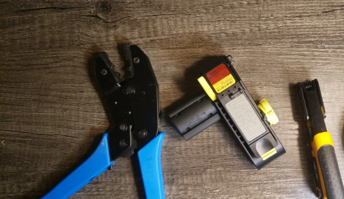
From left to right, there is the cable crimper, cable stripper, and cable cutter. You will also need the bag of BNC parts, shown below.
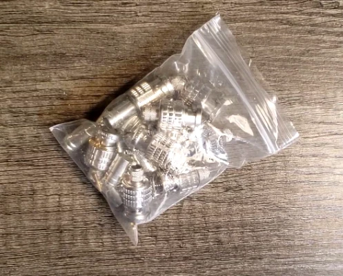
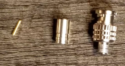
It takes three parts from the bag to make one connector. One each of the pin, ferrule, and shell (from left to right, below) are required.
- Start by cutting the coax cable cleanly, using the cable cutter. Cut as close to the end as possible, so the cable length is maintained.
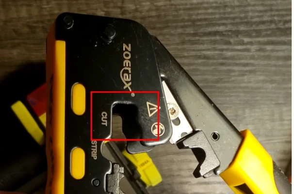
- Strip the cable using the cable stripper.
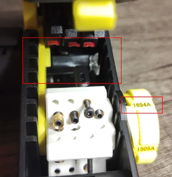
- Ensure the lid of the stripper is open. Tap the stripper against a table and inspect inside to make sure there is no cable debris stuck inside the stripper. Additionally, make sure that the dial on the right side of the stripper is turned to “1694A”. This is the type of cable used in our primary SDI cables. The knob rotates only in one direction.
Warning
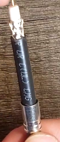
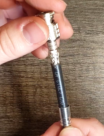
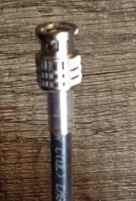
At time of writing, the type of cable used in our SDI cables is not unified on 1694A stock, but this is planned to be the case following the 2026 season. The primary 75-foot sleeved SDI cables utilize this stock (zip-tied to the outside of the braid), for other cables please reach out on Slack for assistance.
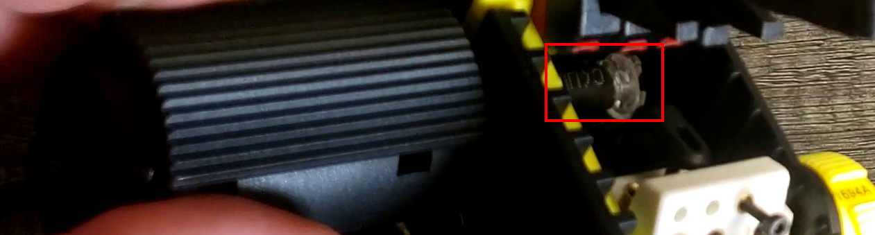
2. Push the cable into the opening on the left side of the stripper until it bottoms out on the clear window on the right side of the stripper.
3. Close the lid, ensuring the latch clicks.
4. Squeeze on the textured grips (seen in the above image) with your left hand and insert your right index finger into the hole on the front end of the stripper.
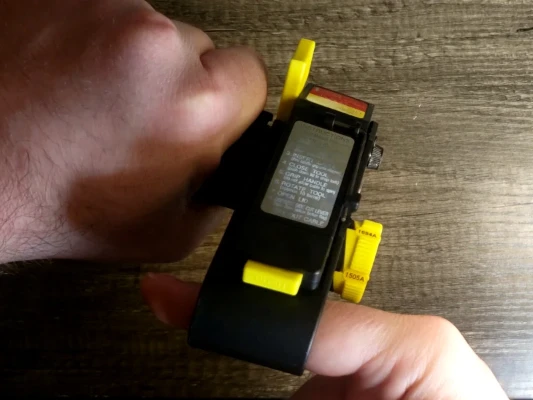
5. Rotate away from you (push index finger up and away from your body to start) 10-12 times, or until no resistance is felt anymore.
6. Continuing to squeeze grips, push the yellow button on the lid to open it. Then, squeeze the yellow flag with your right hand.
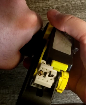
7. Continuing to hold the flag, release the grips with your left hand, then grab the cable and pull it out of the stripper. Some force is required to remove the cable.
8. Tap the stripper upside-down on a table to remove the cable remnants that are still inside.
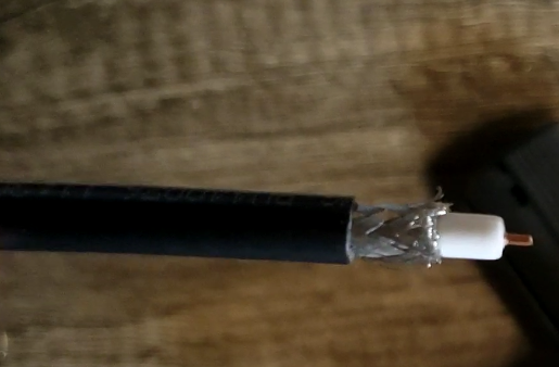
9. Peel the remaining outer jacket (if any remains) away, leaving the cable with a three-layer strip.
- Assemble and crimp the BNC connector using the cable crimper.
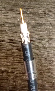
- Place the ferrule on the cable, with the two rings facing away from the end.
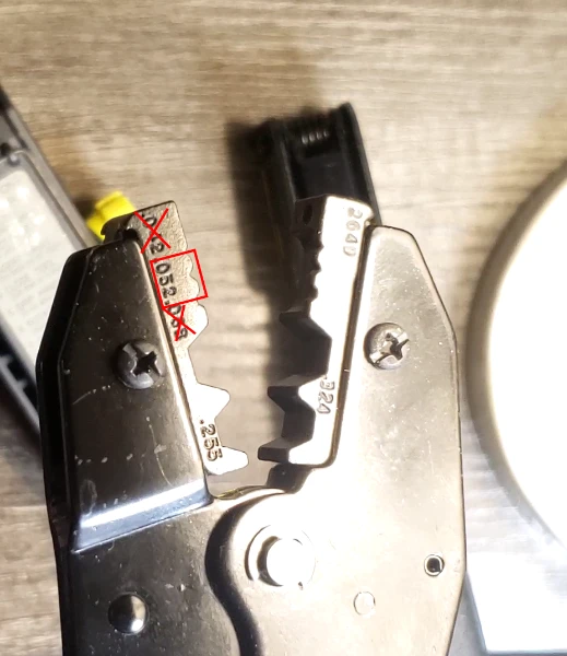
- Place the pin over the center copper conductor. When doing this, ensure the pin is pushed all the way against the white dielectric insulator.
- Crimp the pin onto the copper conductor using the .052” size crimp on the crimper. This is the center of the small crimps.
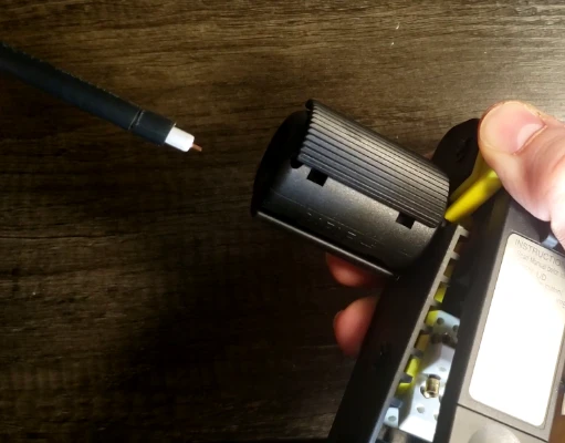
- Place the BNC shell loosely over the pin, such that it extends onto the inner insulator but does not fully seat onto the pin and does not contact the foil and braided shielding.
- Slowly rotate the shell while holding the cable close to the strip point. This will help to separate the foil and braided shield from the inner insulator.
Shell Placement
The shell must go underneath any braided or foil insulation, or compromised signal will result. Continue to rotate, or use another method to separate the foil and braid from the dielectric until the lip of the shell can safely pass underneath the foil.
- Push the ferrule up, sandwiching the exposed shield between the ferrule and the shell. A slight (less than 1/4 turn) rotation can help clean up any “whiskers” left over from stripping.
- Crimp the ferrule onto the shell using the .324” size crimp on the crimper. This is the largest size crimp that the crimper has.
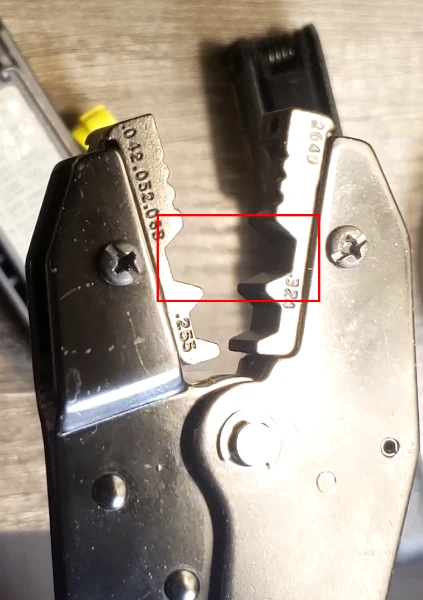
- After crimping with the .324” size crimp, if needed, a partial crimp with the .255” size can be used. If you choose to use this size, do not squeeze past the first click point on the crimper or you may overcrimp and damage the cable.
- Test the crimp by giving a firm tug to the cable end. The connector should remain on the cable.